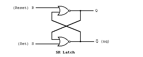
Suppose we were to describe the following SR latch using VHDL as in the following schematic.

We might build an entity like the one that follows.
entity latch is
  port (s,r : in bit;
        q,nq : out bit);
end latch;

architecture dataflow of latch is
begin
  q<=r nor nq;
  nq<=s nor q;
end dataflow;
note: If you are familiar with programming languages, notice that the <=
symbol was chosen carefully to avoid confusion with the variable assignment
operator (usually = or :=)
of typical programming languages. The signal assignment operator in VHDL
specifies a relationship between signals, not a transfer of data as in
programming langauges.
As we saw in the last section, the entity describes the interface to the design. There are four signals s,r,q, and nq that are accessible externally to the design. Again we model the signals in our design with the VHDL data type bit, which can represent two level logic values.
The architecture part describes the internal operation of the design. In the data flow approach we indicated how data flows from the inputs to the outputs. In VHDL this is accomplished with the signal assignment statement. The example architecture consists of two signal assignment statements.
A signal assignment statement describes how data flows from the signals on the right side of the <= operator to the signal on the left side. The first signal assignment in the example tells us that the data coming from signals r and nq flow through a nor gate to determine the value of the signal q. The nor represents a built-in component called an operator, because it operates on some data to produce new data. The second signal assignment, similar to the first, indicates that the signal nq is produced from data (s and q) flowing through (or processed by) the nor operator.
The right side of the <= operator is called an expression. The value of the expression is determined by evaluating the expression. Evaluating the expression is performed by substituting the values of the signals in the expression and computing the result of each operator in the expression.
The previous section is Structural Descriptions - Connected Blocks.
The next section is Data Flow Descriptions - How it Works.