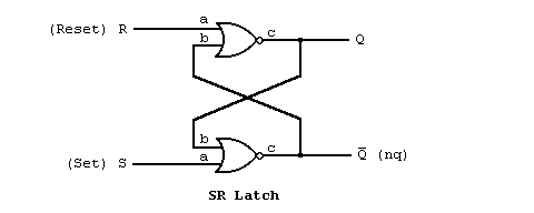
Let's specify the operation of the latch entity used in the previous section by connecting some previously defined entities. The entity declaration for the latch was:
entity latch is
  port (s,r: in bit;
	q,nq: out bit);
end latch;
We will declare an architecture different from the one in the last section that demonstrates the structural approach. To do so, we assume that an entity named nor_gate has been defined that will be used in the design. The schematic for the latch might be
We can specify the same connections that occur in the schematic using VHDL with the following architecture declaration:
architecture structure of latch is
  component nor_gate
    port (a,b: in bit;
	  c: out bit);
  end component;
begin
  n1: nor_gate
    port map (r,nq,q);
  n2: nor_gate
    port map (s,q,nq);
end structure;
The lines between the first and the keyword begin are a
component declaration. It describes the interface of the
entity nor_gate that we would like to use as a component in
(or part of) this design. Between the begin and end
keywords, the first two lines and second two lines define two
component instances.There is an important distinction between an entity, a component, and a component instance in VHDL. The entity describes a design interface, the component describes the interface of an entity that will be used as an instance (or a sub-block), and the component instance is a distinct copy of the component that has been connected to other parts and signals. To compare these with the process of bread board design with off-the-self parts. The entity and architecture is like the data book describing the interface and schematics of how the part works. The component is like the short pin listing that comes with the part to describe how it should be connected. The component instance is the actual part itself, of which you may have many that each operate independently.
In this example the component nor_gate has two inputs (a and b) and an output (c). There are two instances of the nor_gate component in this architecture corresponding to the two nor symbols in the schematic. The first instance represents the top nor gate in the schematic. The first line of the component instantiation statement gives this instance a name, n1, and specifies that it is an instance of the component nor_gate. The second line describes how the component is connected to the reset of the design using the port map clause. The port map clause specifies what signals of the design to connect to the interface of the component in the same order as they are listed in the component declaration. The interface is specified in order as a,b, and then c, so this instance connects r to a, nq to b, and q to c. This corresponds to the way the top gate in the schematic is connected. The second instance, named n2, connects s to a, q to b, and nq to c of a different instance of the same nor_gate component in the same manner as shown in the schematic.
The structural description of a design is simply a textual description of a schematic. A list of components and there connections in any language is sometimes called a netlist. The structural description of a design in VHDL is one of many means of specifying netlists.
The previous section is Structural Descriptions -
Building Blocks.
The next section is Data Flow Descriptions - A first example.